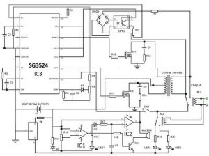
30+ inverter circuit block diagram
Inverter Circuit Diagram The input DC voltage can be turned ONOFF by using power devices like MOSFETs otherwise power transistors. These parts are a full-wave bridge rectifier DC link and an inverter.

The Simplest Function Generator Built On A Breadboard Function Generator Generator Circuit Diagram
A transfer function block diagram of the inverter under the one input source condition is shown in Fig.

. Battery system ac coupled micro backup inverters inverter grid solar diagram block charger tie based compatible. Sine Wave Inverter Control technique Block Diagram The triggering pulses are obtained at the point of intersection of the carrier and a reference signal sine wave. The circuit in this article shows you a simple way to build a 12v to 230v inverter circuit diagram of 100watt power using 555 IC.
Inverter circuit gives Alternating Current AC output from battery Power source but the battery. PV Solar Inverter Circuit diagram. Qasim Hameed Firas Mohammed Ali Al-Raie -32 - Figure 1 4 shows the schematic diagram of the final inverter circuit.
Circuit diagrams of many welding machines available on the market even. You need a solar panel with power rating of 130 watts to get 100 watt of power at the. Download EASYARC ZX7-200 IGBT INVERTER WELDER service manual repair info for electronics experts.
Solar panel power 130 watts. This electrical device that transforms the AC power supply frequency the VFD circuit comprises three parts. High-Voltage Traction Inverter Block Diagram A closer look at the inverter shown in Figure 5 reveals six total semiconductor power switching devices with a gate driver to amplify.
If there is 5VDC then you will want. Solar panel power 100 100 x 30 100 our estimated loss is 30. 650 V78 A30 m were implemented.
Wiring Circuit Diagram For Inverter Grid And Generator - Computers. The 5V DC input voltage of the AT89C51 microcontroller and the 74LS244. 555 is a timer ic which is used to generate time.

Perhaps The Best 124 Light Emitting Diode Circuit Diagram Homeicon Info

Let S Try To Work Out The Proposed 500va Pure Sine Wave Inverter Circuit Layout Elaborately With The Electronic Schematics Sine Wave Electrical Circuit Diagram

Mp2208 Converters 16v 4a 600khz Synchronous Step Down Converter Mps Monolithic Power Systems

Diy Solar Projects For The Home Online Workshop Solar Water Heater Diy Solar Energy Projects Solar Energy Diy

Wiring Theory For Contactors Dc Dc Conv Charger Diy Electric Car Forums
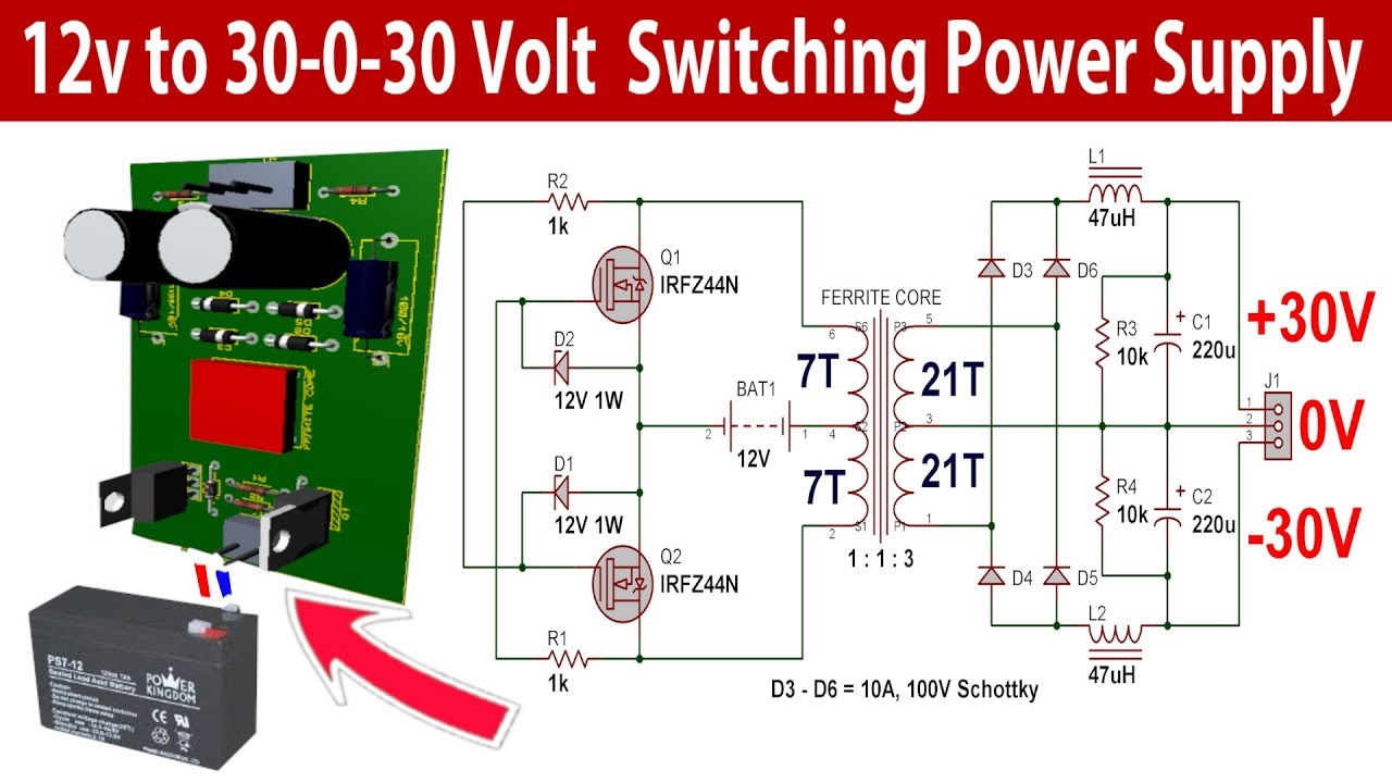
30 0 30 Volt 500w Switching Power Supply For Power Amplifier Youtube Power Supply Circuit Power Amplifiers Circuit Diagram
Pwm Inverter Definition Circuit Diagram Working And Applications
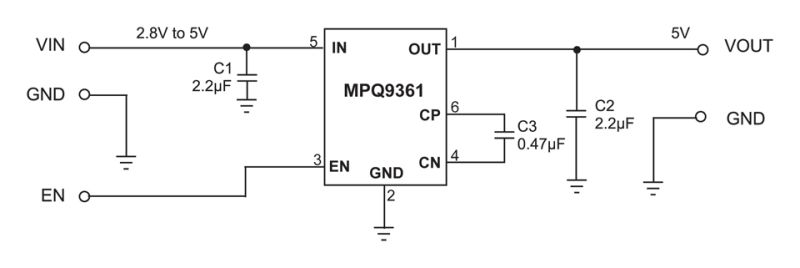
Mpq9361 Industrial Grade High Performance Regulated Charge Pump Mps
![]()
Dc To Ac Inverter Circuit Working Limitations And Applications
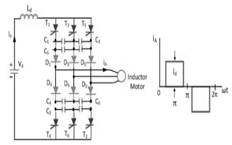
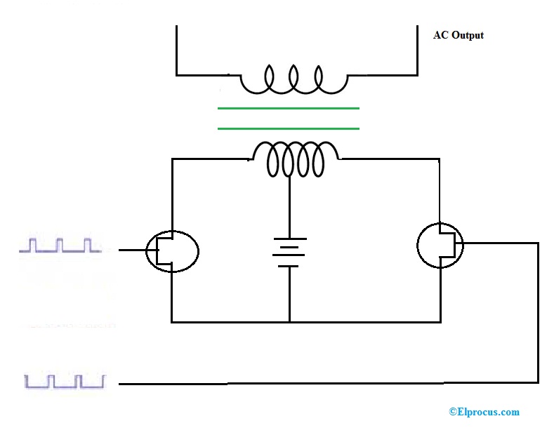
Current Source Inverter Circuit Diagram And Its Advantages
This Article Briefly Describes The 30 Watt Audio Power Amplifier Irf9530 This Principle Is Easy To Understa Power Amplifiers Audio Amplifier Circuit Diagram

Pin On Class D Amplifier

Charge Control Diagram For Wind Turbine Solar Panel System Solar Energy Solutions Diy Wind Turbine Solar Energy Projects
Inverters Working Different Types Circuit Working And Its Applications

Camper Wiring Diagram W 3000w Inverter 600 1200w Solar Diy Solar System Solar Installation Solar Power Batteries
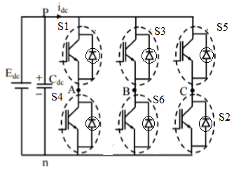
Three Phase Inverter Circuit Working And Its Applications
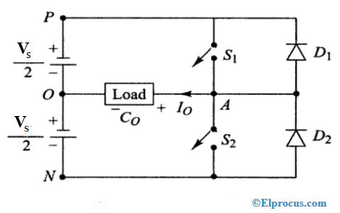
Half Bridge Inverter Circuit Diagram Advantages Its Disadvantages